Thursday, September 26, 2019

Manual Car Washer&Automatic Car Washer

Car Washing 

Car washer is a most commonly used equipment in a garage. It supplies the water under high
pressure through a fl exible pipe and nozzle.
A commonly used car washer has following main parts:
● Electric motor
● Reciprocating water pump
● Water tank
● Spray nozzle
● Flexible water pipe
● Control valve
● Safety valve
● V-belt and pulley
● Pressure gauge

Car washers can be classified as:

● Manual car washers, and
● Automatic car washers (which are generally computerised and costlier)

Manual Car Washer

A manual car washer consists of an electric motor which moves the crank and piston with the help
of a V-belt. A pressure control valve is provided to adjust the pressure of water. The nozzle at the
delivery pipe is able to adjust the amount of water. A storage tank is provided to store the water.
Manual Car Washer

Automatic Car Washer

The first automatic car washes appeared in the late 1930s. Automatic car washes consist of tunnel-like buildings into which customers (or attendants) drive. In this, car is parked on the platform and is manually pre-washed by jet spraying at high pressure and under chassis wash.
Further ph neutral shampoo is spread in form of foam, structure moves on rails along with rotating
brush which cleans the car from top as well as from sides. Drying is done manually with cloth.
Water used is directly dumped into sewage or water recycling plant.
Automatic Car Washer

Applications of Car Washer

Car washers are used for cleaning the cars and other vehicles. The washing is carried out to
remove mud, dust, dirt, grease, wax, oil, fat and other sticky chemicals from the cars.
  1. High pressure pre-wash
  2. Foam Wash
  3. Brushing
  4. Rinsing
  5. Drying

Saturday, August 24, 2019

Air Compressor and function


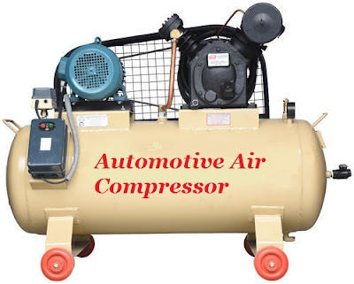
Air Compressor

An air compressor is a machine that converts power (using an electric motor, diesel or gasoline engine, etc.) into potential energy stored in pressurized air (i.e., compressed air). By one of several methods, an air compressor forces more and more air into a storage tank, increasing the pressure. When tank pressure reaches its upper limit the air compressor shuts off. The energy contained in the compressed air can be used for a variety of applications, utilizing the kinetic energy of the air as it is released and the tank depressurizes. When tank pressure reaches its lower limit, the air compressor turns on again and re-pressurizes the tank.There are many methods of air compression and can be divided into either positive-displacement or negative- displacement type compressors.
Air Compressor

Positive Displacement
Positive-displacement compressors work by forcing air into a chamber whose volume is decreased to compress the air. Common types of positive displacement compressors are:

Piston-type air compressors
Rotary screw compressors
Vane compressors
Piston-type air compressors type of air compressors uses the principle in which pumping of air into an air chamber takes place because of the use of constant motion of pistons. They use one way valves to guide air into a cylinder chamber, where the air is compressed.
Rotary screw compressors use positive-displacement compression by matching two helical screws that, when turned, guide air into a chamber, whose volume is decreased as the screws turn. Vane compressors use a slotted rotor with varied blade placement to guide air into a chamber and compress the volume. Vane compressors deliver a fixed volume of air at high pressures.
Negative Displacement
Negative-displacement air compressors include centrifugal compressors. These use centrifugal force generated by a spinning impeller to accelerate and then de-accelerate captured air, which pressurises it.Compressors can also be classified according to the type of pressure:
Low-pressure air compressors , which have a discharge pressure of 150 psi or less.
Medium-pressure compressors, which have a discharge pressure of 151 psi to 1,000 psi.
High-pressure air compressors which have a discharge pressure above 1,000 psi.
Working principle of Air Compressor
Air compressors collect and store pressurized air in a tank, and use pistons and valves to achieve the appropriate pressure levels within an air storage tank that is attached to the motorized unit. There are a few different types of piston compressors that can deliver even air pressures to the user.
Automotive compressors are combustion engine compressors that use the up-and-down stroke of the piston to allow air in and pressurize the air within the storage tank.Other piston compressors utilize a diaphragm, oil-free piston. These pull air in, and pressurize it by not allowing air to escape during the collection period.
Air Compressor
These are the most common types of air compressors that are used today by skilled workers and craftsmen. Before the day of motorized engines, air compressors were not what they are today. Unable to store pressurized air, a type of antique air compressor may be found in the blacksmith’s foundry bellows. Now the air compressor is capable of building extreme pressures in storage tanks capable of storing enormous amounts of pressurized gases for industrial use.
Applications of Air Compressor
Portable air compressor for powering tools, such as jack-hammers.
To supply high-pressure clean air to fill gas cylinders.
To supply moderate-pressure clean air to a submerged surface supplied diver.
To supply moderate-pressure clean air for driving. Some office and school building. pneumatic HVAC control system valves.
To supply a large amount of moderate-pressure air to power pneumatic tools, such as jack-hammers
For filling tyres
To produce large volumes of moderate-pressure air for large-scale industrial processes (such as oxidation for petroleum coking or cement plant bag house purge systems). Most air compressors either are reciprocating piston type, rotary vane or rotary screw type. Centrifugal compressors are common in very large applications. The power of a compressor is measured in HP (Horsepower) and CFM (cubic feet of air per minute). The gallon size of the tank tells you how much compressed air “in reserve” is available. Gas/diesel powered compressors are widely used in remote areas with problematic access to electricity.They are noisy and require ventilation for exhaust gases. Common workshop/ garage compressors are 110-120 Volt or 230-240 Volt. Compressor tank shapes are: “pancake”, “twin tank”, “horizontal”, and “vertical”. Depending on a size and purpose compressors can be stationary or portable.

Wednesday, July 31, 2019

Steering system and Servicing

Steering system

A steering linkage is the part of an automotive steering system that connects to the
front wheels. Steering linkages consist of drag link (pitman arm), tie rod, ball joint,
end joint, arm assembly, torsion bar, steering shock absorber, bushes of steering
axis, steering arm and stub axle.
Steering system
Regular Inspection of steering linkage is necessity to maintain safety and control of
the vehicle. If it is ignored, it may cause fatal accident.

Inspection of steering linkages

  •  Lift the front portion of the car/vehicle,
  • Turn the steering from one end to another end, Check for noise and binding in-steer,
  • If the binding is traced, Remove the drag link connection from steering gear box,
  • Now rotate the steering gear box in both the direction and trace for the binding. If the binding is noticed then it probably lies in the steering gear box
  • If the binding is not traced in steering gear box then problem is in steering linkage,
  •  Check the ball joint/bushes for free movement with thumb pressure and
  • replace the same if necessary,
  • Inspect the ball joint if it is worn out or bellow torned then replace it,
  • Inspect the bushes of the torsion bar and replace it,
  • Inspect the drag link, tie rod for its straightens,
  • Remove the bushing by using special tools and replace the same.
  • Inspect damper/strut for any crack, rust and also check its length if it is not with a specified value then replace it.
  • Check the bushes for wear.
  • Check the coil spring for its length, height and tension.

Precaution

1. Fix the spanner properly.
2. Keep the removed nut bolts properly.
3. Handle the pots carefully.
4. Support the chassis properly with stand.

Manual and Power Steering System

Manual Steering
Vehicle is steered with mechanical efforts and maintains and control road stability.
Different types of steering box are used in automobile vehicle.
  • Worm and roller shaft
  • Worm and nuts
  • Rack and pinion
  • Worm and sector
These all gear boxes are supported with power steering, which helps the driver to
increase his efforts in steering of vehicle.
Manual Steering: Mechanically/Manual operated steering
Procedure for servicing of the manual steering system (Worm and
roller shaft).
To check the working of mechanically/manually operated steering system,
following steps are followed.
1. Conduct the road test and mark the central or the mid position of the road
wheels and the steering gearbox.
2. Now raise the front portion of a car and turn the steering wheel.
3. To check for the binding in the steering.
4. If binding is traced then disconnect the drop arm from the cross shaft of the
steering gearbox.
5. Now again turn the steering and inspect for the binding.
6. If the binding is traced then the fault is in the steering gearbox, and need to
service the steering gear box.
7. Disconnect the electric connections from the steering wheel.
8. Now using specified spanner remove the steering wheel nut from the steering
shaft.
9. Use special tool to remove the steering wheel.
10. Remove the steering gear mounting bolts and dismount the steering gear
box from the chassis.
11. Clean the external portion of the steering box.
12. Remove the side cover from the steering gear box,
13. Now remove the cross shaft from the steering gear box casing,
14. Loosen the steering column bolts and remove it out,
15. Slowly remove the steering shaft from the casing,
16. Wash the components check their wear also check their alignment
17. Replace the worn out components,
18. Assemble the worm shaft and then the cross shaft with their bearing(s).
19. Conduct the road test and assure proper steering alignment.

Rack and pinion type steering gear box:

This type of steering gear is used for light vehicles and in power steering. It occupies
very small space and uses lesser number of linkage components as compare to
worm and wheel type of steering gear.
Steering system

Servicing of the rack and pinion type steering gear box

1. Unthreaded the steering wheel nut using socket, ratchet. Separate the wheel
from steering shaft.
2. Unthreaded the steering rod’s guide nut.
3. Using screwdriver, the screw of gear lever bracket was unscrewed and
separates the gear lever bracket.
4. Separate the guide nut support plate and gear lever bracket.
5. To separate the steering shaft and gear shaft from steering column both nuts of
bracket were loosened.
6. Steering shaft’s lock nut and both was opened with the help of ring spanner and
double ended spanner. Separate pinion from steering shaft.
7. By removing the lock nut of gear rod from support plate, the rod was taken out.
8. Support plate was separated from gear box housing and end plate, using ring
spanner (9/16”)
9. End plate was taken out from steering gear box housing.
10. Loosened the wheel nuts and jacking up the vehicles. Take the front wheels out.
11. Unthreaded the tie rod end nut from both the sides and take out the rubber
boots from steering gear box housing.
12. Using pipe wrench, both the ball joints were taken out from steering rack.
13. Remove the U clamp bolt form the steering column by using socket spanner
and take out the steering assembly.
14. Using socket plier to remove the pinion assembly from the housing.
15. Now slowly push out the rack from the column.
16. Inspect the rack for bend and teeth’s for the wear; also inspect the pinion
assembly for wear.
17. Also check the pinion bearings, splines for the wear.
18. Thoroughly clean the components of steering.
19. Place the rack in the column and place the pinion in housing.
20. Lubricate rack and pinion with silicon grease.
21. Now assemble the rack and pinion assembly on the vehicle with help of
supporting bolts, tighten the same to specified torque.
22. Check the rack play adjustment and adjust the rack with the help of shims/nut.
23. Check the pinion play adjustment if noticed more/less adjust the spacer with
more/less length.
24. Place these.
25. Now slowly turn the pinion and check it for the free movement.
26. Fix the steering wheel as per the aligning mark and tight the nut.
27. Connect the lower and upper steering shaft and fasten it with the pinion
coupling.
28. Carry out central or mid position adjustment and connect the ball joint with
steering shaft.
29. Fix both dust boots over the ball joints and lock it.
30. Tighten the ball joint with specified torque with steering shaft.
31. Conduct the road test and adjust the steering accordingly.

Power Steering

The steering effort at steering wheel turning, two types of power is applied
mainly hydraulic and electronically operated motor.
Steering system

Hydraulic operated power steering

In this type of power steering, fluid is pressurized through a centrifugal pump. This centrifugal pump is driven by the engine crankshaft through v belt. Hydraulic system consist of pump, fluid container,
hoses and steering mechanism having in and out valve connected through pipes and hoses. When the vehicle is moving in straight ahead direction, pump rotates and does not actuate the steering effort, when vehicle takes turn at low speed or in standing condition or parking condition. Pressurized Fluid is forced through the steering worm and rack piston through inlet valve. It helps to steer vehicle easily by reducing steering efforts.

Inspect the power steering

  • Park the vehicle on the level ground
  • Switch off the engine and check the oil level in power steering container
  • It should be between minimum and maximum level
  • Type of fluid is known as power steering fluid
  • Check power steering hose connections for leakage/damages/cracks
  • Check and replace fluid filter at regular interval as per service manual.
  • Inspect the functioning of centrifugal pump in turning of vehicle, if faulty replace the pump
  • Carry out bleeding operation after each service.

 2nd type of Electronic power assisted steering system EPS

EPS uses as electric motor to assist the driver of the vehicle. Steering sensors
detect the position and torque of the steering column and ECU applies assistive
torque via the motor which connect to either steering gear or steering column. This
mechanism is fitted at steering shaft/ worm shaft. It helps in assisting in steering of
vehicle. In this system electrical motor operated advantage of this system is in fuel
efficiency because there is no belt driven hydraulic pump constantly running by the
engine.

Sunday, July 28, 2019

Torque Wrench and Filler Gauge

Torque Wrench

A torque wrench is a tool used to precisely apply a specific torque to a fastener such as a nut or bolt. It is usually in the form of a socket wrench with special internal mechanisms. It was invented by Conrad Bahr in 1918. It was designed to prevent over tightening nuts and bolts. A torque wrench is used where the tightness of nut and bolts is crucial. It allows the operator to measure the torque applied to the fastener so it can be matched to the specifications for a particular application. Torque wrenches are of various types such as digital wrench, angular wrench etc.
Torque Wrench
Torque Wrench

Torque wrenches are often considered and used as “tools” rather than true measuring “instruments”. They provide a “visible” measure of torque (dial indicating, flat beam TW). They are used to control torque in assembly and fastening operations.
Torque Wrench

Filler Gauge

A filler gauge is a tool used to measure gap widths. Filler gauges are mostly used in engineering to measure the clearance between two parts or surfaces.They consist of a number of small lengths of steel of different thicknesses with measurements marked on each piece. They are flexible enough that, even if they
are all on the same hinge, several can be stacked together to gauge intermediate
values. It is common to have two sets for imperial units (typically measured in
thousandths of an inch) and metric (typically measured in hundredths of a
millimetre) measurements.
Filler Gauge
A similar device with wires of specific diameter instead of flat blades is used to set the gap in spark plugs to the correct size; this is done by increasing or decreasing the gap until the gauge of the correct size just fits inside the gap. The lengths of steel are sometimes called leaves or blades, although they have no sharp edge.